Two parts of the South Bend have needed repairs since before the rebuild. There is a tremendous amount of backlash in the cross slide feed screw, 0.07". There is also a set of parts missing from the back gear to keep it locked in position when in use.
The cross slide feed screw was tackled first. The feed screw was removed by first removing the slotted nut holding the handle in place. A pin wrench was used to loosen the screw's locking nut. The screw could then be screwed all the way out of the cross slide nut. The screw's dial had a gap adjacent to the screw's locking nut. The gap was measured at 0.023" with feeler gauges. A brass shim washer was made to take up this gap. A length of brass hex was faced and reduced to 0.67". It was center drilled and drilled up to 3/8" to a depth of 3/16". The parting tool was used to part off a 0.023" washer. The edges were deburred. The lead screw was taken apart and the washer was inserted per the South Bend Lathe Rebuild manual. The lead screw was put back together and screwed into the cross slide nut. As expected the backlash was reduced to 0.05". A new cross slide nut was ordered from Ebay. Luckily the company offers both the normal nut and the modified version for lathes equipped with the taper attachment.
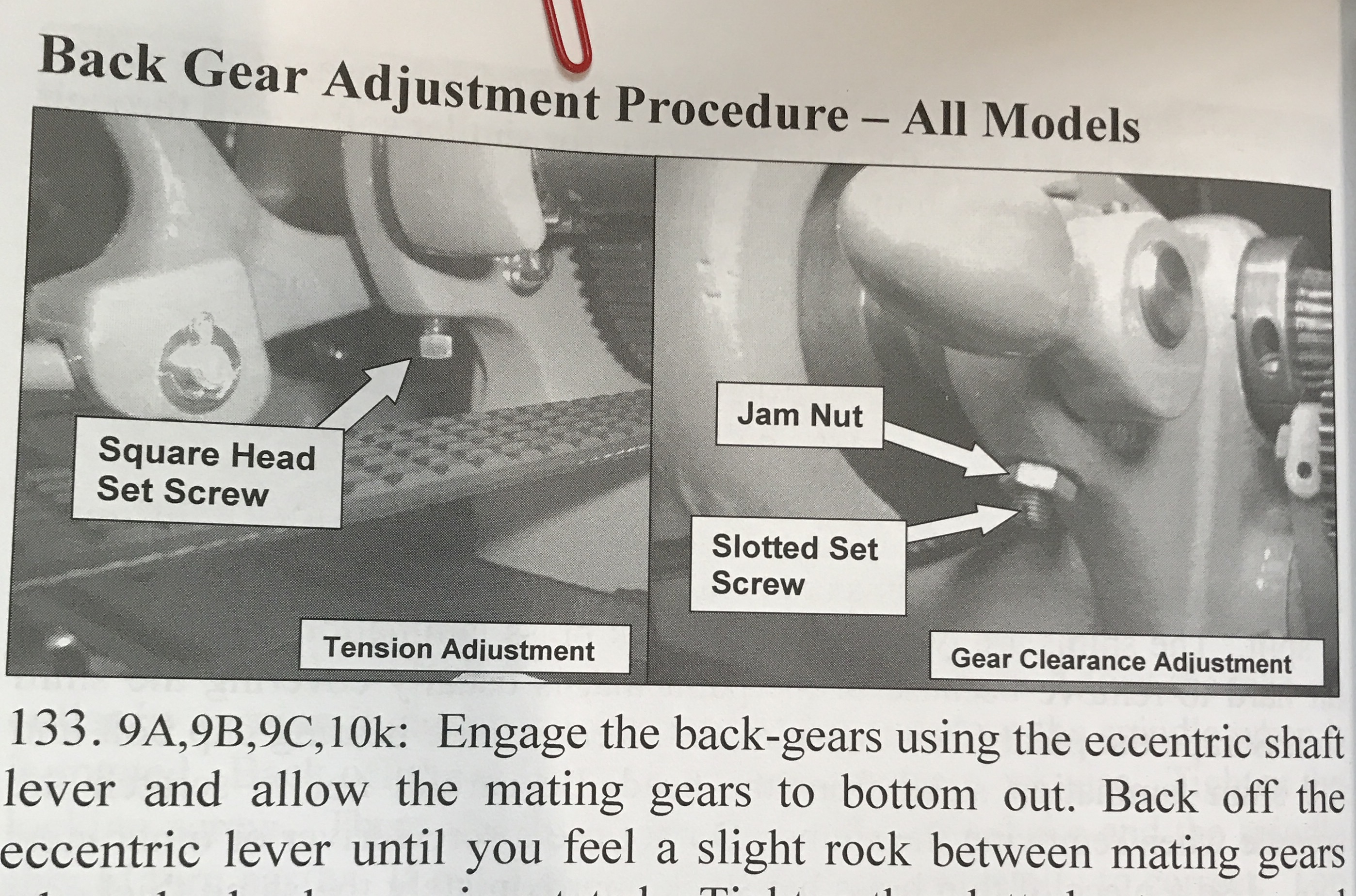
The manual mentioned above was quite confusing with respect to the back gear. It only mentions the one adjusting slotted set screw and locking nut for the 9" lathe. For the 10" it shows both the same screw and locking nut on the distal end as well as a square headed set screw, spring and shoe on the opposite side of the headstock. The former is to adjust the spacing between the gears. The latter is to hold the back gear in place when it is in use. The latter is missing on my lathe.
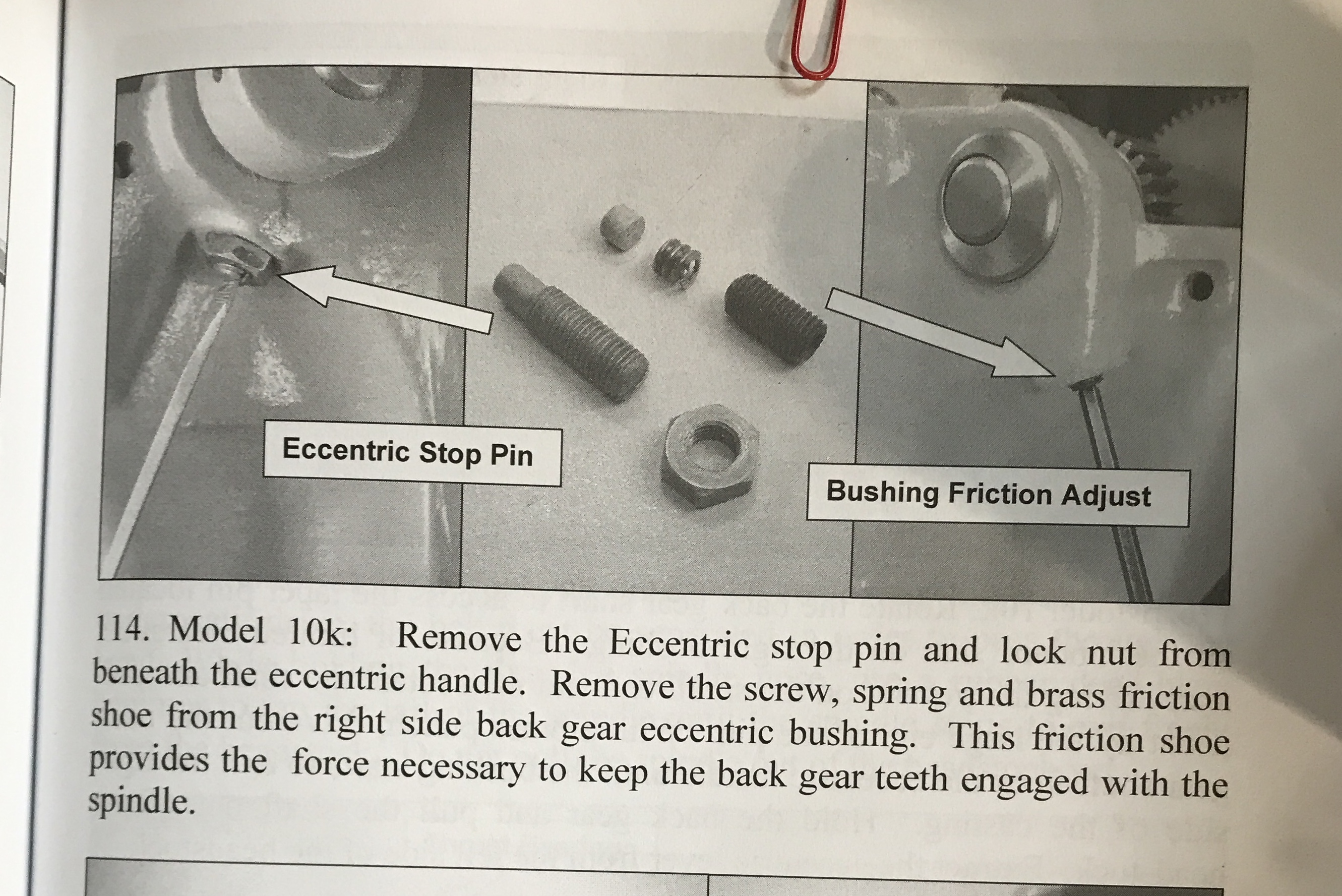
I decided to make a set similar to the parts shown for the 10" lathe. The set screw associated with spring and shoe is the same size and pitch as the set screw I have as shown by screwing it into the opposite hole. The manual indicates a length of 1/2" of threads. (The picture shown is not of a square head set screw!) The screw for the left side is 5/16-24. The shoe shown in the picture is about 1/4" long as is the spring. The spring and shoe should be 0.25" in diameter for a comfortable fit in the threaded hole. The music wire, 0.020", for the spring was ordered today.
The square headed set screw needs to be made. According to the American National Standard on Square Bolts a 5/16" head needs the following dimensions. It is 0.50" across the flats and 13/64" high. The 0.5" seems like it would be too big as this is not a bolt, but a set screw. I will make it the same size as the screw in the lantern tool post, <3/8". Then the same wrench can be used to adjust it. If it is made from 1/2" round stock it will have nicely rounded corners. (0.53" is the diagonal length for a 0.375" square.) I found a stash of key stock that ranges in size from 1/8" to 1/2". It was from Klaus Schmiegel. I don't know how it will machine, but it is certainly worth trying.
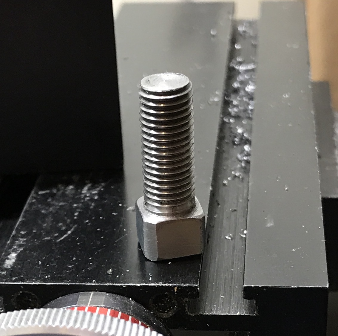
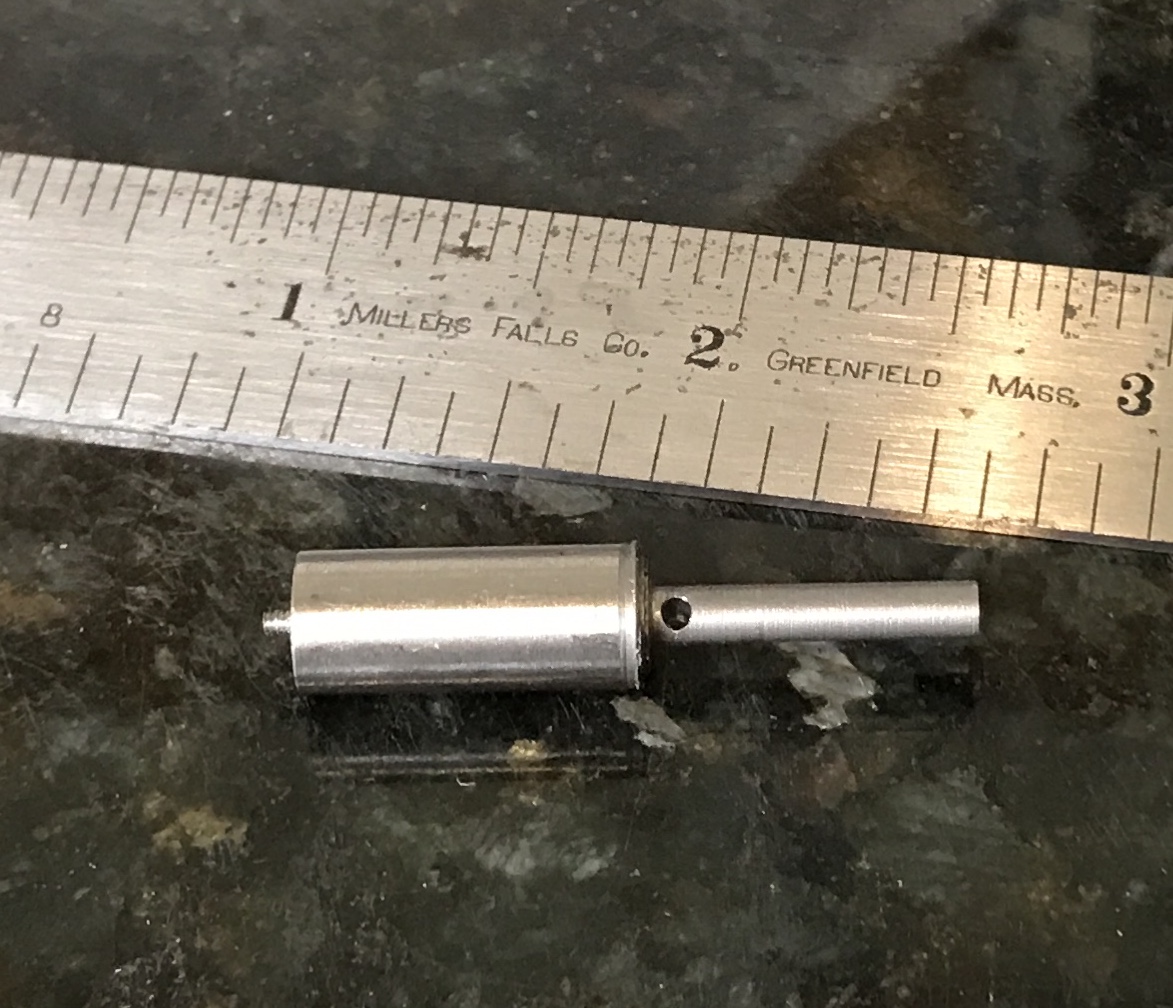
I am not sure exactly what the key stock is made of. It is zinc plated. I cut off a 1 X 1/2" length of the 3/8" key stock. It was held in the four jaw chuck and zeroed in. It was reduced to 0.312" for slightly over 3/4". The surface finish is marginal. The end was chamfered. An attempt was made to start the 5/16-24 die in the lathe, but it not was possible. The die was put in a holder and the part was held in the vise. The die was successfully started. The thread was cut with some difficulty even though a lot of cutting fluid was used. The thread did not fit in the hole in the back gear bracket. The die was tightened and the part rethreaded. Very little material was removed, but the screw fit nicely. About 1/4" of the square end was cut off with a hacksaw. The four edges were rounded somewhat with the lathe tool. The end corners were filed and the flats sanded. The final screw is shown below.
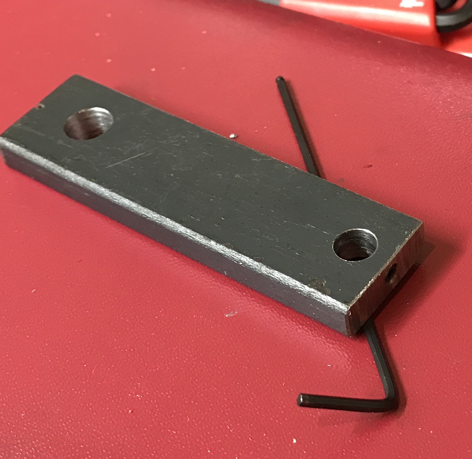
Making the spring is next on the agenda. To make the spring two jigs are needed. The first is a spring wire tensioner. This is a simple device to keep just a bit of drag on the wire as it is wound. A 3/4" bar of 1/4" hot rolled steel was found in the scrap bin. It is a little short of 3" long. The width varied across the length. The rough side was made parallel to the opposite side with the two flute end mill. The bar was drilled on one end through for a 5/16" bolt about 0.5" in from the end. Similarly the other end was drilled for a 1/4" shaft, 1/4" from the end. Both holes were centered across the width. The end of the part with the 1/4" hole was drilled and tapped 6-32. A small set screw was installed. The wire will run through shafts sitting in the two holes.
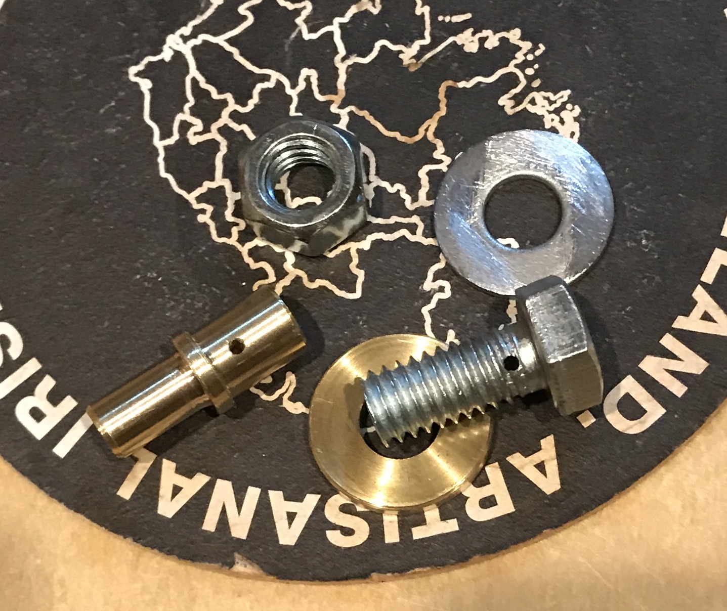
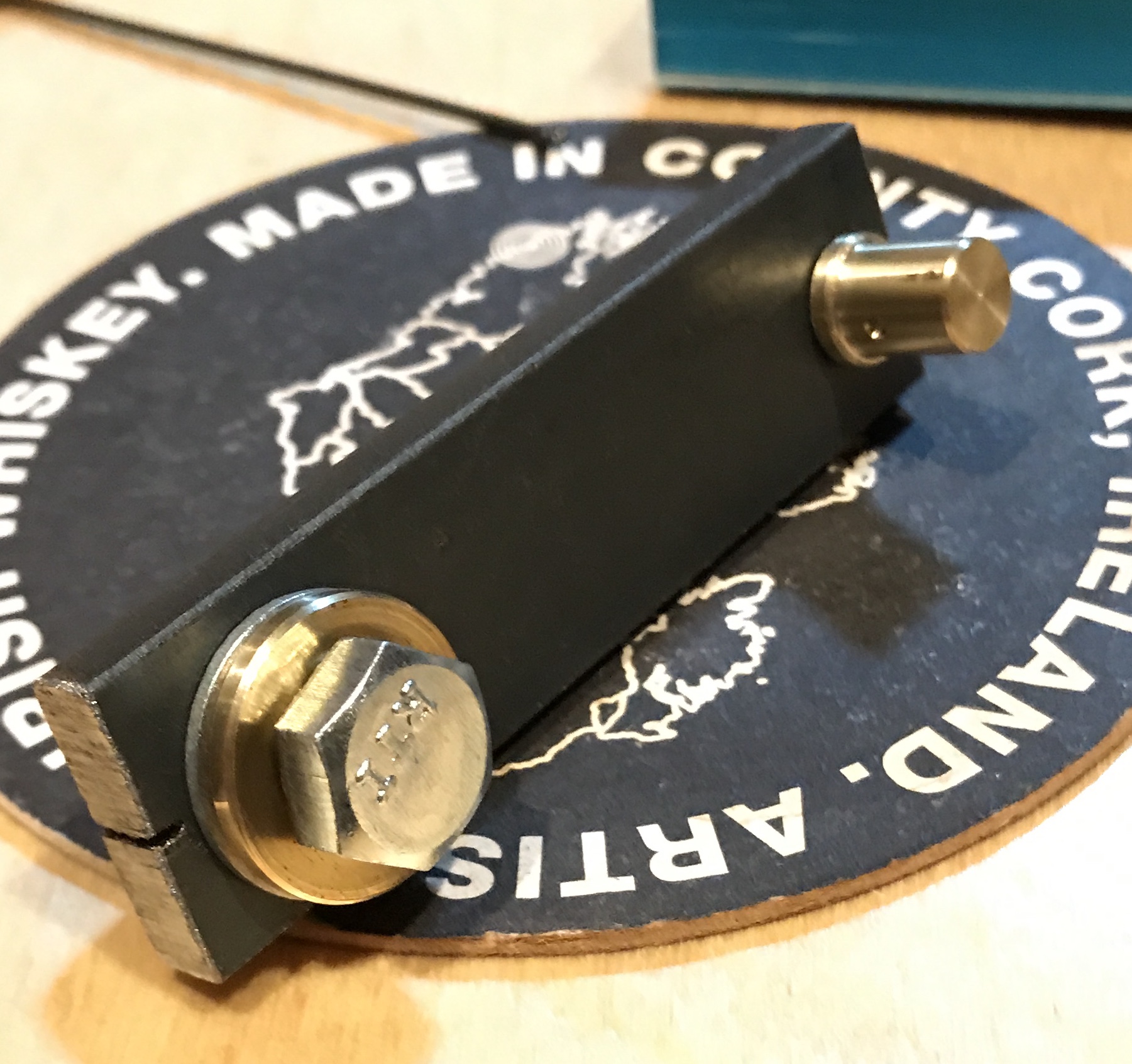
Three more parts were made for the tensioner. A small shaft of brass was reduced to 1/4" for 3/8" and to 5/16" for 3/8" on the opposite end. A small bearing surface was left between the two reduced ends. About 1/16" above this bearing surface on the wider end a small hole was drilled through with a #53 drill. A 5/16" screw was cut off at 11/16" from the head with a hacksaw. A flat was milled on the threads against the head. A hole was drilled through the screw centered on this flat 3/32" from the head again with the #53 drill. A brass washer was quickly made that is 3/32" thick. This group of parts is shown in the first photo below. The assembled tensioner is shown in the second.
The mandrel for the spring needs to account for the approximately 33% increase in spring diameter after removing the spring. The desired OD is 0.25". OD - 2X wire diameter times 67% means the mandrel should be about 1/8" OD. A 1 1/2" length of 3/8" drill rod was faced on one end and center drilled. With the half-center in place 3/4" of the rod was reduced to 0.125". The rod was held in the finger plate. It was drilled through the 1/8" segment close to the 3/8" part with a #53 drill. The photo below shows the completed mandrel.
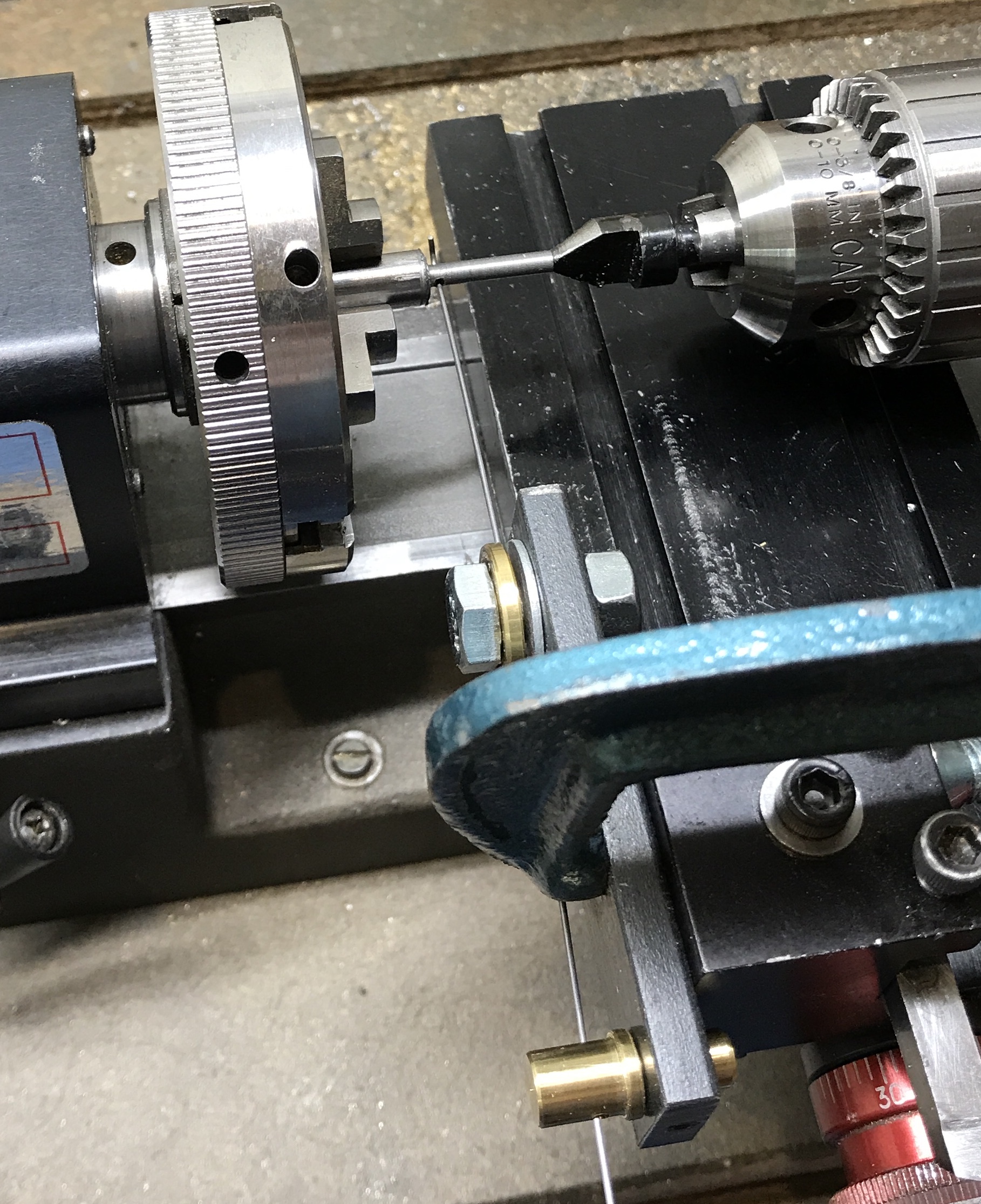
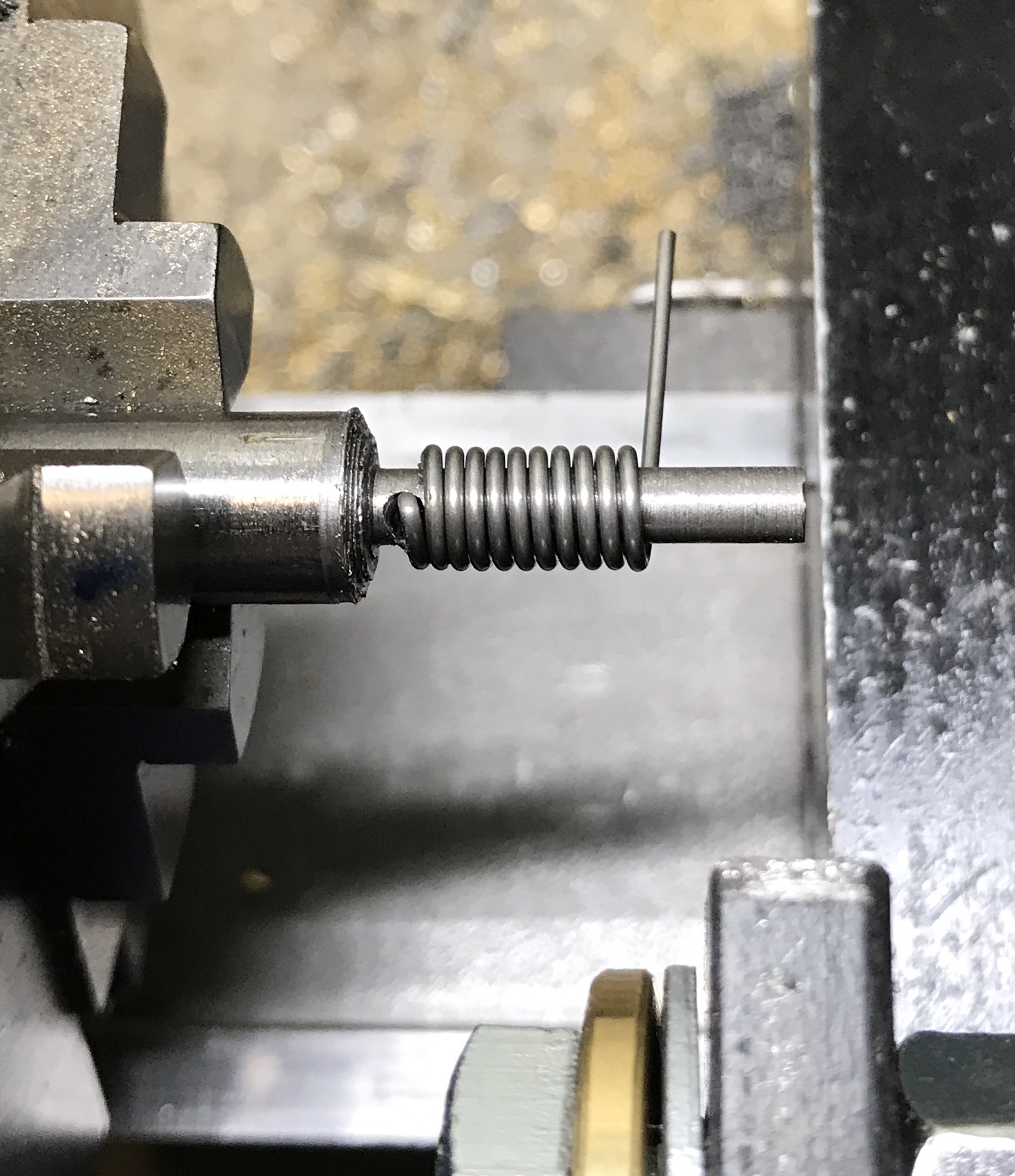
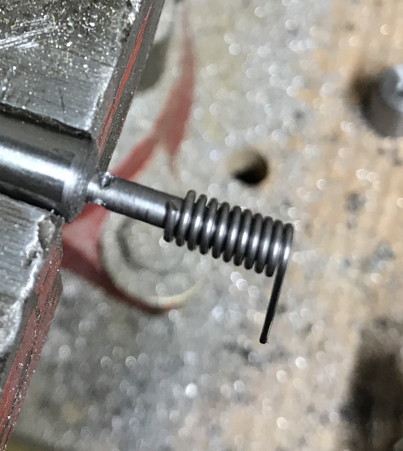
Ready to make the first spring! The tensioner was clamped to the Sherline tool holder with a C-clamp. It was held so the bottom of the tensioner was 9/16" above the bottom of the tool holder. This put the wire roughly on center. The lathe was set up for threading 30 TPI. The mandrel was put in the three jaw chuck and the tensioner was roughly aligned with the hole in the mandrel. A 0.032" wire was slipped through the two holes of the tensioner and through the hole in the mandrel. The tensioner was tightened finger tight. The crank was turned opposite to threading so the spring would be wound away from the headstock. The first spring was a mess. I tried again with the tensioner much closer to the mandrel. This worked perfectly and produced a nice spring, though the coils were very close together. The spring was removed from the mandrel with a cutting disk mounted in the Dremel. The gears were changed to produce 20 TPI and a third spring was made. This spring was also also cut off of the mandrel with the Dremel. The photos below document this process. The last photo shows the second and third springs. The third spring is more open than the second.
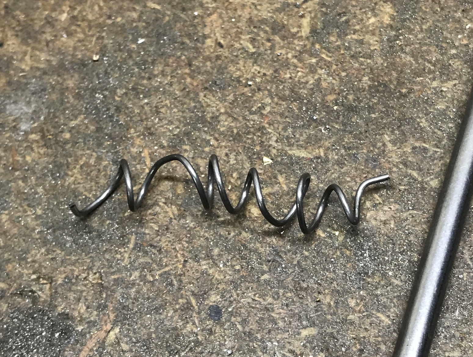
The article suggested 20-40% allowance for mandrel size as the springs loosen a bit when the tension is released. Thus the 33% allowance noted above. Both good springs were 0.205" OD. Theoretical OD is 0.125" plus twice the diameter of the wire or 0.165". This is closer to a 25% allowance, so the mandrel ideally needs to be about 0.175" in diameter. The ends of the spring were cut off at a taper with the Dremel.
Turning the handle counterclockwise as described above does pose one problem. The chuck can come unscrewed. Making the third screw was most easily accomplished by turning the chuck instead of the handle.
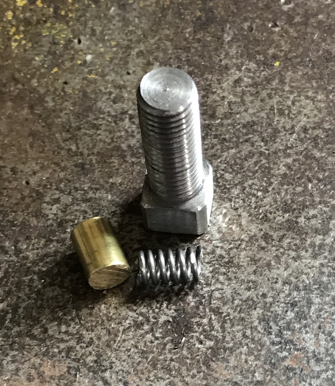
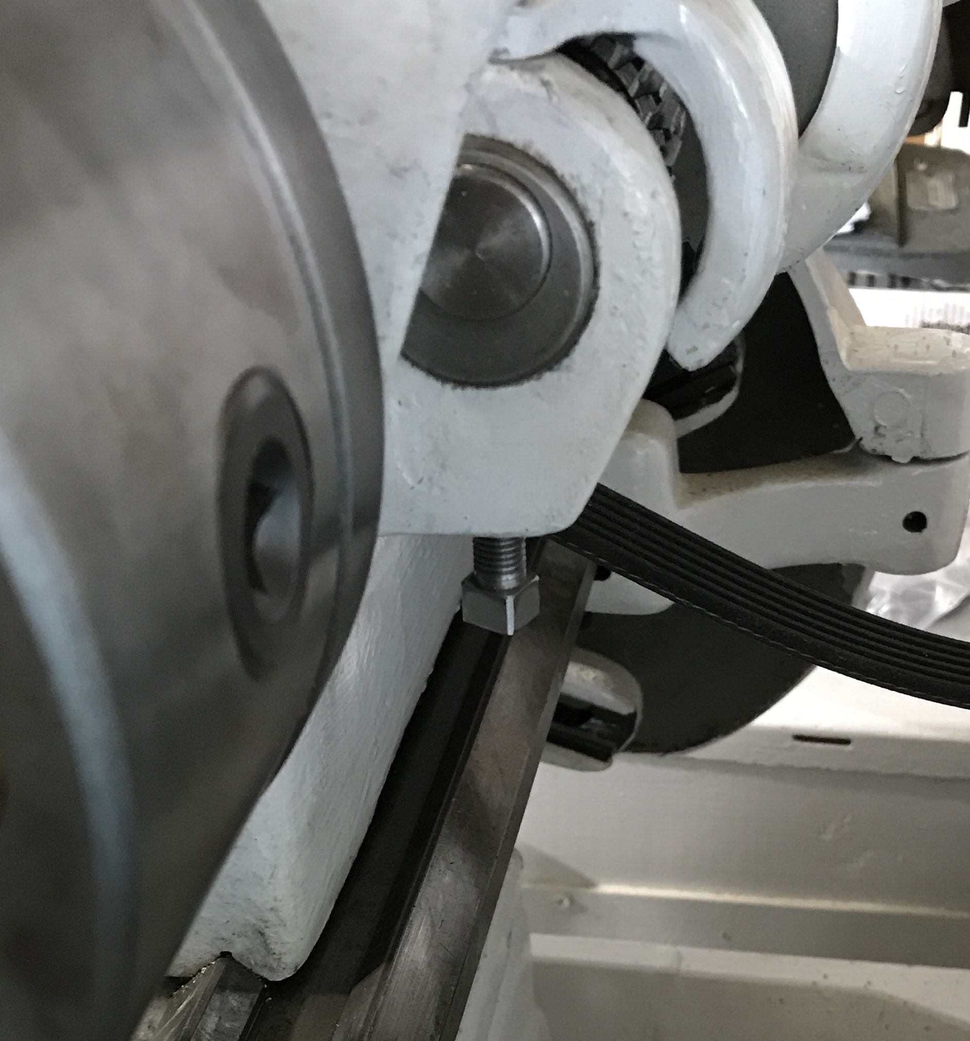
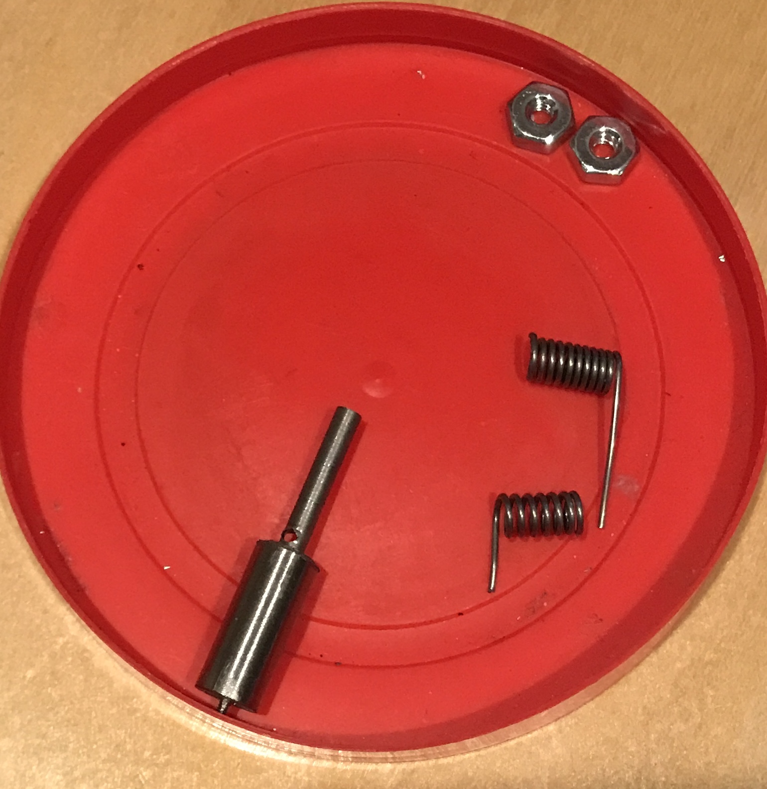
The backgear was completed this afternoon. The set screw with jam nut was installed. The set screw was tightened sufficiently so that there is just a little gear rattle. The jam nut then locked the set screw in place. A shoe was made from a rod of 1/4" brass. The end of the rod was filed with a half round file to put a slight curve on it. The end of the rod was parted off at 3/8". This shoe was pushed up into the hole, followed by the spring, and the square headed screw. The square headed screw was tightened by hand until it felt sufficiently tight to keep the back gear from popping out. The back gear lock was pulled out. The back gear lever was moved to join the back gears. The lathe was turned on. All worked perfectly. There was only a slight gear rattle, so the lever is adjusted properly. The first picture below shows the completed components for the back gear tension adjustment. The second picture tries to show the location of this tension adjustment on the lathe headstock.